

Enhancing Coating Lifetime in Mid-Life Tankers and Bulk Carriers
Dr L.M. Callow
Many of the first double hulled tankers built in the early 1990’s are
reaching the mid-point in their predicted service lifetimes. The very large
coated areas in the ballast tanks will be starting to require serious attention
in the very near future. The present economic conditions in the tanker market
preclude large scale refurbishment and alternative methods have to be evolved
to enhance the coating lifetime until economic conditions improve.
The currently very buoyant bulk carrier market also inhibits the time consuming repairs that may be pertinent. Carefully targeted coating repairs used in combination with the judicious placement of sacrificial anodes, appear to be the answer. However, unless very carefully controlled, this strategy can often result in the very rapid breakdown of the coating repairs.
The answer is to understand the mechanism driving the paint breakdown, carefully measure its extent, locate the weak areas of the coating and then evolve a method for dealing with those particular areas.
Understanding the mechanism and probable progress of the corrosion phenomena present allows surveying to be taken some steps further into the field of prediction. Identifying imminent catastrophic coating failure is vital. Techniques and mechanistic models have been developed to enable a clear and quantitative assessment of the remaining useable ballast tank lifetime to be reached. The ability to make an accurate assessment in this area enables:
1. A cost effective maintenance and repair strategy.
2. Expensive repairs and steel renewals to be avoided.
3. Clear pre-purchase assessments of vessels to be made.
4. Sale or repair decisions to be made on an informed basis.
Breakdown Mechanisms.
Ballast tank steel corrosion and the breakdown mechanisms of coatings are all
electrochemical in nature, with a large cathodic area driving a small anodic
area. The large areas of the flat surfaces are usually the cathode sites, with
the welds and edges being the anodic sites. This results in a strong tendency
for the corrosion current to focus on any areas of weakness or non-uniformity
in the coating.
Coating barrier properties are affected by the electrochemical processes that are occurring in the tank. The resistance of the coating to corrosion remains high for several years over the majority of the surface, but as some areas begin to decline in their resistance with time, this increases the level of electrochemical stress. After a period of time, there is a rapid loss of barrier effect in the flat areas. This generates the large and invisible cathodic site. Identifying and quantifying these cathodic areas is key to any successful maintenance strategy.
Breakdown Time Scales.
Over its lifetime, a coating undergoes a series of changes in its barrier properties.
As a coating ages, it goes through three major stages: initiation, stabilisation
and breakdown. The time that it spends in each stage is extremely variable.
The initiation phase can be said to last between six months and two and a half
years. During this time, the barrier properties tend to increase in a somewhat
erratic manner.
The coating then enters a stabilisation phase where its barrier properties slowly decline over a number of years. When the barrier properties decrease to a certain level, a failure point is reached where catastrophic breakdown is initiated and the electrochemical loading in the ballast tank increases dramatically due to reduced coating barrier properties in the cathodic areas. Changes in the level of coating breakdown are shown schematically in figure 1.
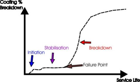
Figure 1. Schematic diagram of ballast tank coating breakdown vs service
life, showing phases of the coating lifetime.
Quantifying Breakdown.
The normal Classification Society method of quantifying ballast tanks gives
three categories, “good”, “fair” and “poor”.
However when a ballast tank has reached a “fair” condition, the
useable lifetime of the coating has probably been exceeded and steel repair
will become inevitable, as the coating will be well out of the “stabilisation”
phase and will be in he “breakdown” phase.
It is important to be able to detect coating breakdown before the point that extensive refurbishment becomes necessary. In order to do this, it is necessary to assess the coating breakdown in a manner that enables the breakdown mechanism itself to be understood.
The vessel structure also needs to be understood in terms of how the breakdown on the edges and welds interacts with that on the flat areas. Once breakdown has initiated it is important to quantify its level and severity. Two methods are available: visual and instrumented assessments.
Visual Quantification of Breakdown.
Traditionally, percentage area charts or scatter diagrams have been used to
determine a percentage breakdown area for the whole ballast tank. Typical charts
are shown in figure 2.

Figure 2. Typical diagrams used for the assessment of coating breakdown.
These charts often look nothing like the real thing, as in coated ballast tanks,
the flat areas rarely breakdown first and corrosion tends to spread from the
edges. To reflect this, a new set of charts has been developed and typical examples
are shown in figure 3.

Figure 3. Examples of new style coating breakdown assessment charts.
The onset of catastrophic failure of coatings is often indicated visually by
weld and edge breakdown. As quantification of these phenomena is of paramount
importance, new linear extent diagrams have been developed to assess the extent
of breakdown in these areas. The edge diagrams shown are also used to quantify
edge calcareous deposit jacking.
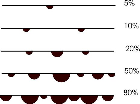
Figure 4. New extent diagrams for assessment of corrosion at edges.
The most important point of the survey is to identify if the coating failure
point has been exceeded. This is usually indicated by the extent of breakdown
exceeding 1% and an increase in the rate of sacrificial anode consumption that
usually results in pitting of the anodes. At this point, maintenance by crew
touch up or repair becomes increasingly more difficult.
Instrumented Quantification of Coating Breakdown.
Instead of frequent close up visual examinations, barrier property measurements
on the flat (cathodic) areas gives the earliest indication that the failure
point has been exceeded. Comparisons over a large number of vessels shows a
good correlation with visual methods.
Instrumented methods of measuring coating barrier properties give more reliable and consistent results. Electrochemical patch probes designed for coating assessment can be used to give a quantitative measure of the quality of the coating.
Measurements of the substrate potential also provide information on the type of corrosion reaction occurring. The combination of both types of instrumented methods allows areas of weakened coating to be located for repair.
Some areas of the tanks begin to fail sooner than others and picking up this failure at the earliest possible time enables preventive remedies to be used that can extend the coating lifetime. Coating failure shows up first in instrumented measurements, then in sacrificial anode consumption rates and finally in visual observations of coating breakdown at welds and edges. A patch probe is shown in use in figure 5.
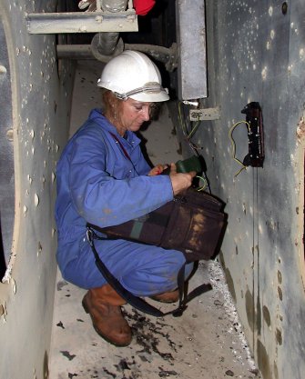
Figure 5. In-situ measurements of coating barrier properties.
These patch probes are the only method to date of locating weak cathodic areas.
The first point at which sites of failure can be detected is usually at the
one year guarantee inspection. From the point of view of middle aged tankers
and bulk carriers, an enhanced coating condition survey immediately prior to
the second special survey is vital and can give:
1. An accurate assessment of the current status of the anti-corrosion measures in place, such as original coatings, effectiveness of repairs, anode condition, etc.
2. A prognosis of probable service lifetime prior to any further repairs.
3. A calculation of balanced sacrificial anode requirement to manage corrosion without causing damage to the coating.
4. An estimate of which areas of the intact coating are active, invisible cathodes and will require repair at the same time as the corroded areas.
5. A proposal of a number of suitable repair or refurbishment strategies, based on the above.
With care and careful management of both the coatings and the cathodic protection anodes, these mid-life vessels should have a viable later life.
Free initial telephone guidance is available on all the topics covered on this web site.
e-mail enquiries sent to the address below will be promptly answered.